
Happy New Year from Electron Machine
With 2017 coming to a close, all of us at Electron Machine wanted to reach out and send our best wishes to our customers, our vendors, and our friends! We hope that 2018 holds success and good fortune for all of you.

Literature Updates for Electron Machine
 Electron Machine Corporation recently updated some of their product, application, and support literature. The new pieces are described and linked below:
Operating and Service Manual for MPR E-Scan
Service manual for the MPR E-Scan, a hybrid-digital critical angle in-line process refractometer. It is used to measure the refractive index of process fluids.
MDS (Monitor Divert System) Color Manual
Service manual for the Monitor Divert System, a BLRBAC (Black Liquor Recovery Boiler Advisory Committee) compliant Black Liquor solids monitoring system designed specifically for Black Liquor recovery boilers.
Brochure for refractometers used to detect sugar levels and properties of jams juices, beverages, dairy products and much more.
Brochure for the MPR E-Scan used for measuring the strength of a chemical when diluted with water or with another chemical.
Brochure for the MPR E-Scan used for measuring the strength of a chemical when diluted with water or with another chemical.
Quality and Process Optimization with Inline Refractometers
 |
| Process refractometer in plant. |
 |
| Process refractometer (Electron Machine Corp.) |
Process refractometers are used for monitoring and controlling process variables in the flowing process media (liquid) . These instruments are used for continual, extremely accurate, real-time substance identification. Through identifying critical factors such as the concentration and purity, manufacturer's can gain tight control over quality can consistency of product. Applications for process refractometers are found in commercial food & beverage, chemical, pulp & paper, and pharmaceutical industries. All share similar processes lines where process refractometry provides real-time, high value information about the product at critical points. These shared processes are:
 |
| Process refractometers are used for food and beverage production. |
Concentration
The measurement of concentrations in compounds of organic chemicals, inorganic chemicals, and total dissolve solids are often required for product consistency. Process refractometers can be calibrated to detect a wide range of dilute chemicals and dissolved solids and be an excellent feedback mechanism for these process variables.
Mixing
Using process refractometers for ingredient mixing to control product quality and production reduces errors and limits variance. Comparing the process media to known reference values, through the use of an inline refractometer, optimizes consistency and maintains quality.
Crystallization
 |
| Process refractometers are critical for making pulp and paper. |
Cleaning
 |
| Process refractometers have many uses in chemical production. |
For more information on industrial process refractometers, contact Electron Machine by visiting https://www.electronmachine.com or call 352-669-3101.
Inline Refractometers Used in Beet Sugar Processing

Juice extraction is done in an agitated hot water diffuser tank that continuously agitates the dilution until the concentration reaches the level that qualifies as juice. Other components and impurities from the beet flesh and skins are also dissolved in the juice which later have to be removed.
 The raw juice is then put through a process call "Carbonatation" that introduces a calcium hydroxide suspension and carbon dioxide under controlled conditions of pH and temperature. This process coagulates impurities and decolorizes the raw juice. The impurities are separated from the clear liquor and calcium carbonate by pressure filtration. The clear liquor is then sent to a multi-stage evaporator to remove water and create syrup.
The syrup is then placed in large boiling pans which boils off remaining water and initiates sugar crystallization. The crystals are then spun to separate them from any remaining mother liquor.
 |
| Electron Machine MPR E-Scan |
In beet sugar refineries, the Electron Machine MPR E-Scan can be used to monitor and control Brix measurement from the beginning of the evaporation stages up to the seed point of crystallization.
Visit Electron Machine at https://www.electronmachine.com or call 352-669-3101.
Measuring Total Soluble Solids with Refractometers
 |
| Inline, process refractometer for beverage production. |
Fruit juices, wine, nectars, and other beverages all contain soluble solids. Total Soluble Solids (TSS) refers to the total amount of soluble constituents of the juice, wine or other beverage. These are mainly sugars, with smaller amounts of amino acids, pectin, and organic acids. For example, approximately 85% of the total soluble solids of citrus fruit are sugars. Because sugar is the most abundant soluble solid, the Brix scale is used by the beverage industry in determining the sucrose equivalent of soluble solids in their products. The term "Brix" or "degrees Brix" is used interchangeably with % sucrose or % soluble solids by weight.
Refractometers are instruments that determine soluble solid concentration by evaluating the solution's refractive index. Changes in direction of a light beam passing through the solution correlate to the amount of dissolved solids in the solution. Basically, the higher the level of soluble solids in the solution, the greater the bending of the light beam. In large scale beverage plants, inline process refractometers are used to control quality and consistency by continuous monitoring of the soluble solid concentration.
For more information about measuring TSS and/or Brix in a commercial beverage production facility, contact Electron Machine by visiting https://www.electronmachine.com or calling 352-669-3101.
Safe Firing of Black Liquor in Black Liquor Recovery Boilers: Refractometer Black Liquor Solids Measurement System
 |
| Recovery Boiler (Courtesy of Wikipedia) |
Information on the BLRBAC can be found here. The full document, as well as other important information, can be found here.
Refractometer Black Liquor Solids Measurement System
4.1 GeneralThe heart of the system for the safe firing of black liquor is the ability to correctly, accurately and reliably measure the solids in the black liquor stream immediately prior to the black liquor guns. To accomplish this solids measurement, refractometers have proven to be effective for black liquor recovery boiler service. As new techniques in measuring solids are developed and proven, they can be considered. For the solids measurements, two refractometers in series must be used. When both refractometers are in service, the requirement for an automatic black liquor diversion can be satisfied by either of the following options:
- If either refractometer reads dissolved solids content 58% or below (62% or below if firing >70% solids per guidelines in 6.4 of this document), an automatic black liquor diversion must take place.
- When both refractometers read dissolved solids content 58% or below (62% or below if firing >70% solids per guidelines in 6.4 of this document), an automatic black liquor diversion must take place.
If the instrument readings disagree on the percent solids by 2% absolute value, an audible and visual alarm must be given.
If one refractometer fails, or is removed from service, black liquor diversion must then be controlled by the remaining in-service instrument; and if this remaining instrument reads 58% or below solids, an automatic black liquor diversion must take place (62% or below solids if firing >70% solids per guidelines in 6.4 of this document). Black liquor shall not be fired if neither refractometer is in service. The refractometers should be part of a specifically integrated system adapted to the black liquor service, and include a system to monitor their operation and indicate trouble or failure of the individual refractometer. Refractometers used without such a monitoring system can fail unsafe and can give improper and unsafe dissolved solids readings under certain conditions.
4.2 Refractometer Control System Functions
The refractometer control system shall be capable of performing the following functions:
1. Monitor the positive (+) and negative (-) supply voltage of each refractometer independently. The refractometer's supply voltage shall be maintained within the predetermined minimum and maximum limits for safe operation.
2. Monitor the lamp voltage or lamp output of each refractometer independently. The refractometers’ lamp voltage must be within the predetermined minimum and maximum limits for safe operation.
3. Monitor the signal amplitude (if chopper circuit devices are used) of each refractometer independently. Each refractometer's signal amplitude must be maintained within the predetermined minimum and maximum limits for safe operation.
4. Monitor the liquor temperature at each refractometer’s sensing head independently assuring that each refractometer's liquor temperature is within the predetermined minimum and maximum limits for safe operation.
5. Monitor the automatic prism cleaning timer system of each refractometer. The sensor output circuit, prior to the hold circuit, should go negative or adequately decrease during the purge cycle.
6. Monitor the automatic prism cleaning timer system to assure that the purge occurs within the predetermined time.
7. Monitor the cooling water to each refractometer sensing head to assure that cooling water is not lost to a sensing head.
If any of these malfunctions (Items 1 through 7) occur, the following action shall be initiated:
a) An alarm shall be activated, identifying the refractometer and circuit at fault.
b) The refractometer shall be electrically removed from the refractometer control system.
c) The remaining “good” refractometer shall remain in service.
8. Compare the refractometer meter outputs. If a difference of 2% (absolute value) solids or greater exists between refractometer readings, an alarm shall be activated.
9. Performs a black liquor diversion, if one refractometer is removed from service or fails in prism wash, and the remaining refractometer fails or reads a solids of 58% or less.
10. Monitor all cables from the refractometer and the components of the control system. If any cable is cut or removed, an alarm shall be activated.
11. Provide primary alarm or diversion functions by a means other than the refractometer indicating meter’s contacts.
12. Have the capability to allow the manual removal of either refractometer from service retaining the remaining refractometer in full service for diversion purposes.
13. Require a manual reset following a black liquor diversion or malfunction of the refractometer control system.
14. Monitor the position of the sensing head isolation valves. A partially closed or closed valve shall activate an alarm and remove the refractometer from service.
15. Initiate a low solids alarm signal from each refractometer at 60% solids or at 70% solids if firing >70% solids per guidelines in 6.4 of this document.
16. Prohibit the simultaneous washing of the individual refractometers.
17. Require manual restoration of a refractometer which has been removed, either automatically or manually, from service.
18. Have provisions for manual prism washing.
19. Require an automatic switch to single refractometer diversion (for systems set to require both refractometers read low solids to divert – dual refractometer diversion) when one refractometer is in a prism wash cycle. Automatic return to the chosen dual refractometer diversion will occur after completion of the prism wash cycle.
All of the above functions may not apply to all refractometer control systems since some refractometers:
a) Do not utilize cooling water,
b) Have sensing heads that are not affected by liquor temperature, etc.,
c) May have differences in electronic circuitry.
4.3 Refractometer Control System - Controls & Indicators
The refractometer system shall be equipped with the following controls and indicators:
1. Reset switch.
2. Switch or other means to manually remove either refractometer from service.
3. Visual solids display for each refractometer.
4. Status lights indicating “in service”. “inoperative” and/or “malfunction” for the individual refractometer and status of diversion valve.
4.4 Refractometer Control System - Alarms and Indicators
The recommended alarms and indicators of the refractometer control system are:

4.5 Installation Requirements
1. The refractometers shall be installed in series.
2. The refractometer sensing heads shall be installed in such a manner that the individual sensing heads can be taken out of service or removed without having to valve off the liquor piping or open bypass valves.
3. All cabinets, wiring, etc., shall be suitable for the atmosphere and service conditions normal to a recovery boiler installation.
4. The refractometer sensing heads shall be installed so that the y are accessible and readily serviceable.
5. The refractometer sensing heads may be installed in any position on a vertical pipe run. On a horizontal run of pipe, the sensing heads must be installed on sides of the pipe. The reason for this is to ensure that the prisms are always covered with liquor.
6. The electrical power supply to the refractometer control system shall be from a dependable (stable) source.
7. A dependable supply of cooling water of satisfactory capacity must be provided for refractometers requiring sensing head cooling water.
8. Dry oil-free instrument air shall be provided to the refractometer sensing heads to prevent and control condensation in the heads.
9. A steam supply source of sufficient capacity shall be provided to meet flow, and minimum and maximum pressures requirements. All installation requirements may not apply to all refractometers and refractometer systems.
4.6 Refractometer Problems
The three major causes of refractometer trouble or failure are:
1. Loss of cooling water and its effect on the sensing head.
2. Lack of reliability of the prism wash.
3. Condensation in the sensing head.
These may not apply to all refractometers due to differences in construction and circuitry.
4.7 Cooling Water Loss
It is of vital importance that the loss of cooling water be detected. This may be done through a temperature sensing element or flow monitor which shuts down the refractometer involved.
Damage to the sensing element of a refractometer does not occur instantaneously, but it is essential that the system detect abnormal temperatures due to cooling water loss, flow blockage, etc., and that the cooling water be promptly restored.
The individual refractometer manufacturer’s instruction and maintenance manuals shall be consulted with reference to: potential damage to the sensing element; identification of a damaged element; how and when to replace a damaged element.
4.8 Prism Wash
The time interval between prism washes may vary with the black liquor composition. It is recommended that the minimum wash period be 7-10 seconds of wash every 20 minutes. Short duration washes at more frequent intervals are more effective than long washes at long intervals. Ideally, steam pressure for prism washing should be 35 psig above the black liquor pressure, plus the pressure required to open the protective check valve.
Awareness must be maintained of the effect of changes to the prism wash programming variables. Various refractometer systems have the capability to adjust: condensate drain time, steam on time, recovery time and interval between wash time. It may be possible to configure the system to have the total time that both refractometers are in their wash cycle represent a significant percentage of operating time. If one refractometer is out of service for repairs and the remaining refractometer is in prism wash, black liquor solids are not being monitored. Prism wash should be minimized to that needed to maintain the system.
If high pressure steam is used, it may abrade the prism. If only high pressure steam is available, a reducing valve shall be used.
The refractometer prism must have a clear polished optical surface, and if it becomes abraded, it must be replaced.
If the prism wash system has not operated properly and the prism becomes coated, it must be removed and properly cleaned.
4.9 Condensation in Sensing Head
Condensate may build up in the refractometer sensing head and if this occurs, the instrument operation will be erratic.
The procedure for determining this condition and for the elimination of excessive moisture in the sensing head is not the same for all refractometers. The manufacturer’s instruction and maintenance manuals shall be consulted and followed carefully.
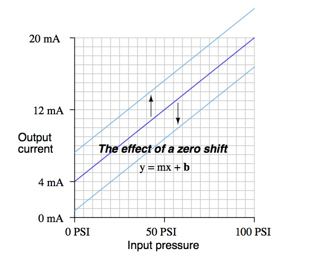
4.10 Refractometer Calibration Standardization (Zero Offset) to Off-Line Test
A Refractometer Standardization (“zero shifting” or “bias adjustment”) is an adjustment of the refractometer calibration curve to an off-line test to account for un-dissolved solids and/or changes in the black liquor chemistry. This is normally performed while the instrument is actively measuring black liquor solids.
All refractometers shall be verified against a reliable periodic off-line test. (See Chapter 6 – Off-Line Black Liquor Solids Measurement)
The refractometers shall be standardized:
1. On initial start-up of the recovery boiler.
2. At any time it is felt or known that one of the refractometers may be deviating from the known black liquor solids content.
3. Any time there is a 2% difference between refractometers.
The reading of the refractometers shall be checked against the moisture analyzer or microwave analyzer at two hour intervals (8 hour intervals if firing above 70% solids), and the moisture analyzer or microwave analyzer shall be checked by the TAPPI Standard Method, T650-om-05, weekly.
All refractometer standardization changes shall be entered in the recovery boiler “log book.”
4.11 Refractometer Calibration
A Refractometer Calibration involves placing two or more “samples” onto the sensor to generate a refractive index vs. dissolved solids curve. This is typically performed utilizing calibration oils or electronically (depending on supplier) in a controlled environment, while the sensing head is off of the process line.
Calibration procedures shall be done in a manner that does not affect the system’s ability to automatically perform a black liquor diversion utilizing the remaining (active) in-service refractometer. Improper procedures, or those that defeat the monitoring system described in Chapter 4, can result in the system failing in an unsafe condition. Refer to the manufacturer’s appropriate procedures.
If the continuous solids monitor refractometer differs from the off-line test field measurement by more than 2% on an absolute basis, the off-line test results must be confirmed and then if required the continuous monitor refractometer should be standardized and/or recalibrated according to the manufacturer’s recommended procedures. Repeated errors may indicate a failure of a refractometer component. Refer to the manufacturer’s recommendations for repair or replacement.
Get to Know Electron Machine Corporation
Electron Machine Corporation, headquartered Umatilla, FL, manufactures industrial, inline, process refractometers. As a vertically-integrated manufacturer, we have complete control over the time it takes to manufacture our instruments providing the highest levels of service and support to our customers. Superb quality control is attained by adapting modern technology and practices to existing designs. These include in-house microprocessor and DSP software design, surface-mount PC card design and assembly, 3D CAD/CAM designing, CNC machining, and MIG/TIG welding. Additionally, our founder's innovative nature is still with us as we continue to research and develop new products.
Learn more about Electron Machine at https://www.electronmachine.com or by calling 352-669-3101.
Learn more about Electron Machine at https://www.electronmachine.com or by calling 352-669-3101.
Technical Sales Representatives: The Often Underutilized Asset
|
| Work with your technical sales rep. It will pay off in ways you haven't imagined. |
Consider these contributions:
Product Knowledge:
Sales engineers, by the nature of their job, are current on new products, their capabilities and their proper application. Unlike information available on the Web, sales engineers get advanced notice of product obsolescence and replacement. Also, because they are exposed to so many different types of applications and situations, sales engineers are a wealth of tacit knowledge that they readily share with their customers.
Experience:
As a project engineer or leader, you may be treading on fresh ground with a refractometry requirement for your current assignment. You may not have a full grasp on how to handle a particular challenge presented by a project. If this is the case, call in the local technical sales representative - there can be real benefit in connecting to a source with past exposure to your current requirement.
Of course, sales engineers will be biased. Any solutions proposed are likely to be based upon the products sold by the representative. But the best sales people will share the virtues of their products openly and honestly, and even admit when they don’t have the right product. This is where the discussion, consideration and evaluation of several solutions become part of achieving the best project outcome.
Whatever your stake in an upcoming or ongoing project, it's highly recommended you develop a professional, mutually beneficial relationship with a technical sales expert, a problem solver. Look at a relationship with the local sales engineer as symbiotic. Their success, and your success, go hand-in-hand.
PID Control: The Basics
 |
| PID diagram (courtesy of Wikipedia) |
Many types of PID controllers exist on the market and are used for controlling temperature, pressure, level and flow. PID control is also used in industrial, inline refractometers to control process variables such as Brix, Percent Solids, Dissolved Solids, Specific Gravity Units, and Refractive Index.
Here is a brief explanation of the three actions that make up PID control.
Proportional Control Action (P): The controller output responds in proportion to error signal. The characteristic equation for this action is:
Today's process controllers are much easier to set the PID, thanks to auto-tuning algorithms. What used to be a very time consuming and tedious job can now be done with the push of a button and allowing the controller to "learn" the process dynamics. PID controllers minimize error and optimize the accuracy of any process.
For more information on the use of closed loop control with industrial inline process refractometers. contact Electron Machine Corporation by visiting http://www.electronmachine.com or calling 352-669-3101.
Proportional Control Action (P): The controller output responds in proportion to error signal. The characteristic equation for this action is:
- Where, Kp is called proportional gain, e is the error magnitude and B is the output from controller when there is no error. It is also called bias.
- In a proportional controller, the value of gain is set as required by the process and can be varied from 0 to ∞.
Integral Control Action (I): The control system will respond if the error is present over a period of time. This type of control action is called Integral Control Action. The integral action is defined mathematically as:
- Where, e= error, Ti= Time interval of integral action.
- Purpose of integral action is to provide adequate control action on varying demands of process. In this type of action, output varies as per the time integral of error. This action does not exist independently and always associated with proportional control.
Derivative Control Action (D): To achieve a stable process, wide proportional band and low integral action are set. Due to these settings, the control system can be too slow. If large system disturbances occur over a wide interval, PI controllers are inadequate. These large system disturbances can be managed if the controller output responds not only to the magnitude of deviation, but also to the rate of change of deviation. Derivative control action is that control action.
Today's process controllers are much easier to set the PID, thanks to auto-tuning algorithms. What used to be a very time consuming and tedious job can now be done with the push of a button and allowing the controller to "learn" the process dynamics. PID controllers minimize error and optimize the accuracy of any process.
For more information on the use of closed loop control with industrial inline process refractometers. contact Electron Machine Corporation by visiting http://www.electronmachine.com or calling 352-669-3101.
Understanding Error in Process Measurement
The three major category of errors regarding measurement are gross errors, systematic errors, and random errors. The first two categories of error, gross and systematic, are related to the two main elements of process control: controller and instrument. Gross errors are a product of the process controller or operator incorrectly evaluating the instrument value, with the best prevention of gross error being careful review of data both while recording and interpreting it.
Systematic errors impact every reading from a particular instrument, and are typically cause for instrument recalibration. Zero errors, where the instrument does not return to the predetermined zero value after each reading, are systematic errors because the same error in measurement is being displayed each time. Lastly, random errors impact instrumentation readings due to causes which are either unknown or simply unpredictable, meaning the error is both not able to be duplicated and is not a result of gross error. Random errors can be challenging to deduce due to both their singularity and their potential lack of a clear cause.
The previously mentioned zero error, also known as a zero shift calibration error, is typified by the resulting readings being offset at the same percentage. For example, a pressure transmitter which is functioning incorrectly as the result of a zeroing error can be corrected by a corresponding zero adjustment. After the adjustment and the transmitter being calibrated back to the correct zero point, the error will disappear. Another common type of systematic error is span shift calibration error. Unlike the zero error, span error can impact readings from the instrument repeatedly, but not necessarily identically. Similarly, by correcting the corresponding setting on the transmitter, in this case the span adjustment, the instrument can be correctly programmed once again by measuring the readings against a properly configured reference.
Hysteresis error occurs when the instrument in question returns erroneous responses as the input variable changes. The antidote to this kind of systematic error is to check the instrument against a pre-defined set of calibration points, first by increasing the input, and then subsequently decreasing the input in sequence to determine how the instrument responds as the input changes. Mechanical friction has been known to be a common culprit for hysteresis errors.
Understanding the capabilities and limitations of whatever instrument is relied upon for delivering process information is essential to successful operation.
Bleaching of Pulp in the Paper Making Process

The purpose of the bleaching process is to enhance the physical and optical qualities (whiteness and brightness) of the pulp by removing or decolorizing the lignin. Two approaches are used in the chemical bleaching of pulps. One approach called brightening, uses selective chemicals, such as hydrogen peroxide, that destroy chromatographic groups but do not attack the lignin. Brightening produces a product with a temporary brightness (such as newspaper) that discolors from exposure to sunlight or oxygen. The other approach (true bleaching) seeks to almost totally remove residual lignin by adding oxidizing chemicals to the pulp in varying combinations of sequences, depending on the end use of the product. This creates a longer lasting (sometimes permanent) whiteness, but it weakens the fibers and reduces sheet strength. The most common bleaching and brightening agents are chlorine, chlorine dioxide, hydrogen peroxide and sodium hydroxide.
Typically, the pulp is treated with each chemical in a separate stage. Each stage includes a tower, where the bleaching occurs; a washer, which removes bleaching chemicals and dissolved lignins from the pulp prior to entering the next stage; and a seal tank, which collects the washer effluent to be used as wash water in other stages or to be sewered. Bleaching processes use various combinations of chemical stages called bleaching sequences.
The first stage in the bleaching process is the chlorination stage, whose primary function is to further delignify the pulp. Chlorine reacts with lignin to form compounds that are water-soluble or soluble in an alkaline medium, which aids in delignifying the pulp before it proceeds to the next bleaching stage.
The next stage after chlorination is typically the extraction stage. This stage and the remaining stages serve to bleach and whiten the delignified pulp. The extraction stage removes the chlorinated and oxidized lignin by solubilization in a caustic solution.
Chlorine dioxide is often used in bleaching, either in the chlorination stage (as a substitute for some of the chlorine usage - chlorine dioxide substitution) or as an additional chlorine dioxide stage. Chlorine dioxide has 2.63 times greater oxidizing power (on a pound per pound basis) than chlorine and is used for nearly all high brightness pulps.
The next stage is the actual bleaching stage. Hypochlorite is a true bleaching agent that destroys certain chromophobic groups of lignin. It also attacks the pulp so high cellulose degradation occurs in Kraft pulp. Application of hypochlorite to Kraft pulp is usually used only as an intermediate stage of the sequence or to produce semi-bleached pulps. In the bleach process, residual chlorine must be removed through washing in vacuum washers.
Abstracted from Washington State
Air Toxic Sources and Emission
Estimation Methods
Air Toxic Sources and Emission
Estimation Methods
Sulfite Pulping

The two main types of chemical pulping are the more common sulfate pulping (most commonly known as Kraft pulping) and sulfite pulping. Kraft pulping accommodates a variety of tree species, recovers and reuses all pulping chemicals, and creates a paper with a higher sheet strength. Sulfite pulp, however, is easier to bleach, yields more bleached pulp, and is easier to refine for papermaking. The major difference between the two types of chemical pulping is the types of chemicals used to dissolve the lignin.
Sulfite Pulping
The concept of sulfite pulping was created in the United States in 1867, however it was not used in a mill until 1874 by a Swedish chemist who was probably unaware of the U.S. Patent (MacDonald, 277). Sulfite pulping produces a lighter pulp than Kraft pulping. It can be used for newsprint, and when bleached can be used for writing papers and for the manufacture of viscose rayon, acetate filaments and films, and cellophane.
Description of Process
Sulfite pulping follows many of the same steps as Kraft pulping. The major difference in sulfite pulping is that the digester “cooks” with a mixture of H2SO3 (sulfurous acid) and HSO3 ion in the form of calcium, magnesium, sodium, or ammonium bisulfate). The pulp continues on through the same processes as in the Kraft pulping process.
However, the chemicals separated from the pulp in the washers may or may not go into a recovery process. Chemical recovery in sulfite pulping is practiced only if it is economical. If chemical recovery does occur the liquor goes through an evaporator and then to a recovery furnace. Here, smelt is not formed, but ash and SO2 are formed.
Abstracted from Washington State
Air Toxic Sources and Emission
Estimation Methods
MPR E-Scan Deemed RoHS Compliant and Earns CE Marking

RoHS stands for Restriction of Hazardous Substances. RoHS, also known as Directive 2002/95/EC, originated in the European Union and restricts the use of specific hazardous materials found in electrical and electronic products.
This certification applies to each portion of the MPR E-Scan (IS), which includes the Console, Cable, Barrier Box, and Sensing Head; along with all components that each of these major subassemblies of the MPR E-Scan contain.
For more information, please contact Electron Machine at 352-669-3101 or by visiting this link.
Paper Manufacturing: Kraft (Sulfate) Pulping
Abstracted from Washington State Air Toxic Sources
and Emission Estimation Methods
and Emission Estimation Methods
Pulping is the term used for the process which separates wood fibers. Chemical pulping, dissolving the lignin in the wood to create a pulp, is the most commonly used pulping process. Chemical pulping creates higher sheet strength than mechanical pulping; however, yields 40 to 50 percent pulp, where mechanical pulping yields 95 percent pulp.
The two main types of chemical pulping are the more common sulfate pulping (most commonly known as Kraft pulping) and sulfite pulping. Kraft pulping accommodates a variety of tree species, recovers and reuses all pulping chemicals, and creates a paper with a higher sheet strength. Sulfite pulp, however, is easier to bleach, yields more bleached pulp, and is easier to refine for papermaking. The major difference between the two types of chemical pulping is the types of chemicals used to dissolve the lignin.
The Kraft process was developed in Germany in 1879 and was first applied to a Swedish mill in 1885. The resulting paper was much stronger than any paper previously made, and therefore the process was named “Kraft”, (German and Swedish for “strength”). Kraft pulping creates dark brown paper which is used for boxes, paper bags, and wrapping paper. Kraft pulp can also be used for writing paper and paperboard when bleached, and for diapers when fluffed.
The three main steps involved in Kraft pulping are:
- Digestion: wood chips are cooked
- Washing: black liquor is separated from the pulp
- Chemical recovery: chemicals are recovered from the black liquor for reuse
- Digestion
Relief gases are vented continuously from the digester, which helps remove air and other non- condensable gases and reduce the pressure at blow, when the pulp is discharged to the blow tank. After the cooking process, the pulp and black liquor (the chemical mix left after the cooking process) are discharged to a blow tank.
By-products can be recovered from the digestion process. For example, turpentine distills with water out of the blow tank and the evaporators and is separated to be used. The resin acids and fatty acids dissolved from the wood form sodium soaps which are skimmed off the black liquor from storage tanks, evaporators, and black liquor oxidation tanks, and then acidified with sulfuric acid to form tall oil.
Before the washing process, the pulp is usually sent to deknotters, screens used to remove knots (large pieces of fiber not completely broken down in the digester).
- Brownstock Washing
All the washer types use water (fresh or recycled) and are usually placed in series to achieve higher removal efficiency.
The rinsed pulp is screened for oversize particles and then excess water is removed. This is done in a gravity thickener (more commonly known as a decker).
- Chemical Recovery
The first step in recovering the chemicals from the black liquor is evaporation. This removes excess water from the black liquor and maximizes the fuel value for the recovery furnace.
There are two types of evaporators generally used in the chemical recovery process: direct (DCE) and indirect (NDCE) contact evaporators. Some types of DCE include the multiple-effect evaporator (most common), flash evaporation and thermocompressor evaporation. DCE use heat from direct contact with the recovery furnace flue gases, while NDCE uses indirect contact.
Black liquor oxidation is needed after DCE, but not after NDCE. After DCE, the black liquor is normally oxidized with air to control the sulfide level and prevent the release of odorous compounds. This is done by countercurrently passing the black liquor through an air stream using a porous diffuser, sieve tray tower, packed tower or agitated air sparge. The oxidation reaction converts sodium sulfide to sodium thiosulfate.
After NDCE or black liquor oxidation, the black liquor is then forced through spray nozzles into the recovery furnace, where it is burned providing heat to generate steam. This also conserves the inorganic chemicals, which create a molten smelt on the floor of the furnace.
The molten smelt, composed of sodium sulfide and sodium carbonate, is drained from the recovery furnace hearth through smelt spouts. In a smelt dissolving tank, the smelt is quenched with water, producing green liquor.
Sodium carbonate from the smelt is then converted to sodium hydroxide in the causticizer by adding calcium hydroxide. The calcium carbonate resulting from the reaction precipitates from the solution and is collected and sent to the lime kiln where it is converted to lime (calcium oxide). The calcium oxide is then slaked to produce calcium hydroxide for reuse in the causticizer.
Hybrid-Digital Process Refractometer

Process refractometers are used for monitoring, controlling, and recording the concentration of dissolved solids in a process media. They accurately measure refractive index and temperature of the process media and provide a visual display in units specific to that process (i.e. Brix, Percent Solids, Dissolved Solids, SGU, R.I.).
The MPR E-Scan is a hybrid-digital critical angle refractometer. It is used to measure the refractive index of process fluids and may be used as an error indicator or an integral part of a complete process control system.
The MPR E-Scan is calibrated and temperature compensated to your process specifications. It is ready for installation and immediate use when received. Calibration procedures are available to change system parameters and allow the refractometer to measure different process fluids.
How It Works: Hybrid-Digital Measurement
 Energy radiated from the LED passes through the prism surface to be reflected off a mirror to the prism-to-process interface. The light reaching this interface intersects the same interface over a series of angles specifically chosen to include the critical angle (Ic) for the process being measured. Light intersect- ing the interface at an angle greater than critical angle is refracted into the solution. Light intersecting the interface at less than critical angle is reflected up out of the prism up to the digital CCD linear array to be scanned.
The resolution of each sensing head is maximized by selecting the angle of the prism for the measurement and temperature range of the process.
 |
| MPR E-Scan |

Isolation Valve Adapter and Safeguard Tool Demonstration
Plant personnel safety is extremely important to Electron Machine. Our Isolation Valve Adapter has a proven track record for safety and reliability for safe removal of our process refactometer sensing heads from a pressurized pipeline. Continuing toward our goal for absolute safety, EMC designed and developed the EMC Safeguard Tool, a device designed to further increase safety should abnormal situations arise when removing a sensing head from the process pipe line. Check out the demonstration below for a full understanding.
For more information, visit http://www.electronmachine.com or call 352-669-3101.
For more information, visit http://www.electronmachine.com or call 352-669-3101.
HART Communication Protocol
 |
| (Image courtesy of Lessons in Industrial Instrumentation and Tony R. Kuphaldt and shared under Creative Commons 4.0 International Public License). |
HART instruments have the capacity to perform in two main modes of operation: point to point, also known as analog/digital mode, and multi-drop mode. The point to point mode joins digital signals with the aforementioned 4-20 mA current loop in order to serve as signal protocols between the controller and a specific measuring instrument. The polling address of the instrument in question is designated with the number ì0î. A signal specified by the user is designated as the 4-20 mA signal, and then other signals are overlaid on the 4-20 mA signal. A common example is an indication of pressure being sent as a 4-20 mA signal to represent a range of pressures; temperature, another common process control variable, can also be sent digitally using the same wires. In point to point, HART’s digital instrumentation functions as a sort of digital current loop interface, allowing for use over moderate distances.
HART in multi-drop mode differs from point to point. In multi-drop mode, the analog loop current is given a fixed designation of 4 mA and multiple instruments can participate in a single signal loop. Each one of the instruments participating in the signal loop need to have their own unique address.
Since the HART protocol is a standardized process control industry technology, each specific manufacturer using HART is assigned a unique identification number. This allows for devices participating in the HART protocol to be easily identified upon first interaction with the protocol. Thanks to the open protocol nature, HART has experienced successive revisions in order to enhance the performance and capabilities of the system relating to process control. The standardization of “smart” implementation, along with the ability to function with the legacy 4-20 mA technology and consistent development, has made HART a useful and popular component of the process measurement and control industry framework.
Overview of Chemical Recovery Processes in Pulp & Paper Mills
 |
| Figure 1 |
The production of kraft and soda paper products from wood can be divided into three process areas:
- Pulping of wood chips
- Chemical recovery
- Product forming (includes bleaching)
 |
| Figure 2 |
The purpose of the chemical recovery cycle is to recover cooking liquor chemicals from spent
cooking liquor. The process involves concentrating black liquor, combusting organic compounds, reducing inorganic compounds, and reconstituting cooking liquor.
Cooking liquor, which is referred to as "white liquor, is an aqueous solution of sodium hydroxide (Na01) and sodium sulfide (Na2S) that is used in the pulping area of the mill. In the pulping process, white liquor is introduced with wood chips into digesters, where the wood chips are "cooked" under pressure. The contents of the digester are then discharged to a blow tank, where the softened chips are disintegrated into fibers or "pulp. The pulp and spent cooking liquor are subsequently separated in a series of brown stock washers: Spent cooking liquor, referred to as "weak black liquor, from the brown stock washers is routed to the chemical recovery area. Weak black liquor is a dilute solution (approximately 12 to 15 percent solids) of wood lignins, organic materials, oxidized inorganic compounds (sodium sulfate (Na2SO4), sodium carbonate (Na2003)), and white liquor (Na2S and Na0H).
In the chemical recovery cycle, weak black liquor is first directed through a series of multiple-effect evaporators (MEE's) to increase the solids content to about 50 percent. The "strong. (or "heavy") black liquor from the MEE's is then either oxidized in the BLO system if it is further concentrated in a DCE or routed directly to a concentrator (NDCE). Oxidation of the black liquor prior to evaporation in a DCE reduces emissions of TRS compounds, which are stripped from the black liquor in the DCE when it contacts hot flue gases from the recovery furnace. The solids content of the black liquor following the final evaporator/concentrator typically averages 65 to 68 percent.
Concentrated black liquor is sprayed into the recovery furnace, where organic compounds are combusted, and the Na2SO4 is reduced to Na2S. The black liquor burned in the recovery furnace has a high energy content (13,500 to 15,400 kilojoules per kilogram (kJ/kg) of dry solids (5,800 to 6,600 British thermal units per pound {Btu/lb} of dry solids)), which is recovered as steam for process requirements, such as cooking wood chips, heating and evaporating black liquor, preheating combustion air, and drying the pulp or paper products. Particulate matter (PM) (primarily Na2SO4) exiting the furnace with the hot flue gases is collected in an electrostatic precipitator (ESP) and added to the black liquor to be fired in the recovery furnace. Additional makeup Na2SO4, or "saltcake," may also be added to the black liquor prior to firing.
Molten inorganic salts, referred to as "smelt," collect in a char bed at the bottom of the furnace. Smelt is drawn off and dissolved in weak wash water in the SDT to form a solution of carbonate salts called "green liquor," which is primarily Na2S and Na2CO3. Green liquor also contains insoluble unburned carbon and inorganic Impurities, called dregs, which are removed in a series of clarification tanks.
Decanted green liquor is transferred to the causticizing area, where the Na2CO3 is converted to NaOH by the addition of lime (calcium oxide [Ca0]). The green liquor is first transferred to a slaker tank, where Ca0 from the lime kiln reacts with water to form calcium hydroxide (Ca(OH)2). From the slake, liquor flows through a series of agitated tanks, referred to as causticizers, that allow the causticizing reaction to go to completion (i.e., Ca(OH)2 reacts with Na2CO3 to form NaOH and CaCO3).
The causticizing product is then routed to the white liquor clarifier, which removes CaCO3 precipitate, referred to as "lime mud." The lime mud, along with dregs from the green liquor clarifier, is washed in the mud washer to remove the last traces of sodium. The mud from the mud washer is then dried and calcined in a lime kiln to produce "reburned" lime, which is reintroduced to the slaker. The mud washer filtrate, known as weak wash, is used in the SDT to dissolve recovery furnace smelt. The white liquor (NaOH and Na2S) from the clarifier is recycled to the digesters in the pulping area of the mill.
At about 7 percent of kraft mills, neutral sulfite semi-chemical (NSSC) pulping is also practiced. The NSSC process involves pulping wood chips in a solution of sodium sulfite and sodium bicarbonate, followed by mechanical de-fibrating. The NSSC and kraft processes often overlap in the chemical recovery loop, when the spent NSSC liquor, referred to as "pink liquor," is mixed with kraft black liquor and burned in the recovery furnace. In such cases, the NSSC chemicals replace most or all of the makeup chemicals. For Federal regulatory purposes, if the weight percentage of pink liquor solids exceeds 7 percent of the total mixture of solids fired and the sulfidity of the resultant green liquor exceeds 28 percent, the recovery furnace is classified as a "cross-recovery furnace.'" Because the pink liquor adds additional sulfur to the black liquor, TRS emissions from cross recovery furnaces tend to be higher than from straight kraft black liquor recovery furnaces.
Industrial Inline Refractometers for Sucrose, Fructose and Dextrose

In sugar refineries, the MPR E-Scan can be used to monitor and control Brix measurement from the beginning of the evaporation stages up to the seed point of crystallization.
The suggested adapter for most installations is either a 316S/S in-line type adapter or a 316S/S vacuum pan adapter. If coating may be an issue, a steam or hot water wash nozzle can be provided.
Sanitary-type adapters designed and manufactured to appropriate 3-A Sanitary Standards are also available if needed.
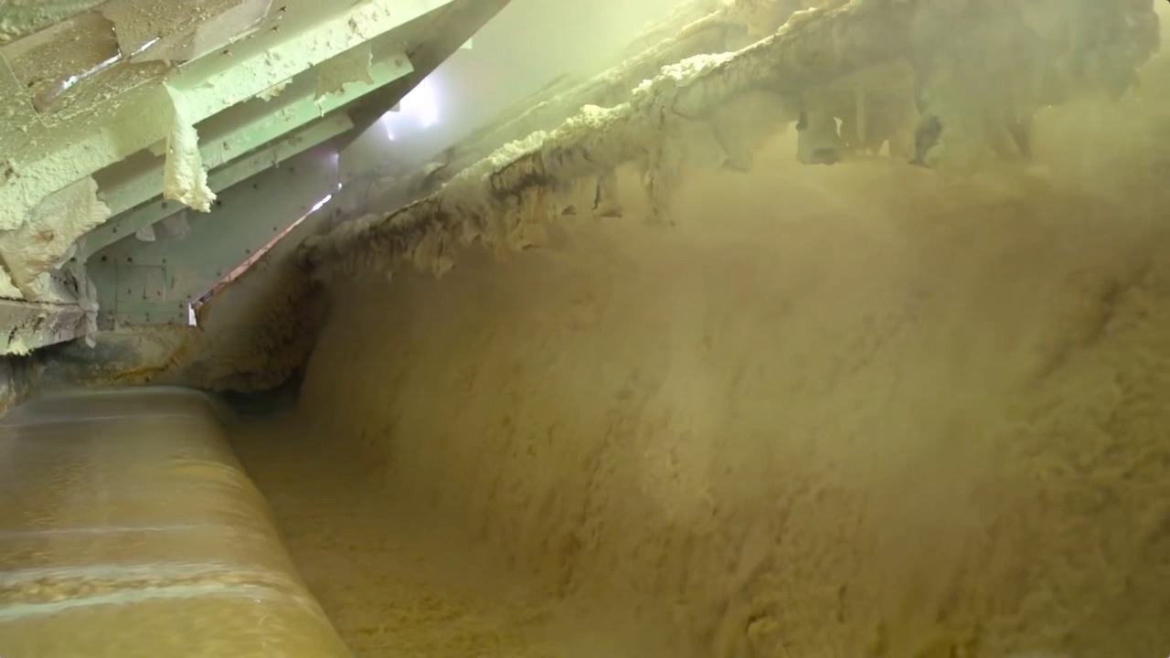
Industrial Refractometers in Action: Pulp & Paper Mill
This video below highlights various applications for inline refractometers in a pulp and paper mill.
The Electron Machine Corporation pioneered the use of refractometers to accurately measure black liquor dissolved solids nearly 50 years ago. Our long history with this application has resulted in numerous design features that specifically address problems associated with this harsh process measurement. Electron Machine refractometers have been accurately measuring green liquor solids in the paper industry for more than 30 years.
For more information visit http://www.electronmachine.com or call 352-669-3101.
Introduction to Industrial Instrumentation
 |
| Engineer adjusting a process controller measuring the refractive index of a process. |
The first step, naturally, is measurement. If we can’t measure something, it is really pointless to try to control it. This “something” usually takes one of the following forms in industry:
- Fluid pressure
- Fluid flow rate
- The temperature of an object
- Fluid volume stored in a vessel
- Chemical concentration
- Machine position, motion, or acceleration
- Physical dimension(s) of an object
- Count (inventory) of objects
- Electrical voltage, current, or resistance
- Refractive Index
This final control device usually takes one of the following forms:
- Control valve (for throttling the flow rate of a fluid)
- Electric motor
- Electric heater
 |
| Process control loop |
Industrial measurement and control systems have their own unique terms and standards. Here are some common instrumentation terms and their definitions:
Process: The physical system we are attempting to control or measure. Examples: water filtration system, molten metal casting system, steam boiler, oil refinery unit, power generation unit.
Process Variable, or PV: The specific quantity we are measuring in a process. Examples: pressure, level, temperature, flow, electrical conductivity, pH, position, speed, vibration.
Setpoint, or SP: The value at which we desire the process variable to be maintained at. In other words, the “target” value for the process variable.
Primary Sensing Element, or PSE: A device directly sensing the process variable and translating that sensed quantity into an analog representation (electrical voltage, current, resistance; mechanical force, motion, etc.). Examples: thermocouple, thermistor, bourdon tube, microphone, potentiometer, electrochemical cell, accelerometer.
 |
| Example of a transducer. In this case, a Refractive Index transducer. |
instrumentation signal, and/or performing some sort of processing on that signal. Often referred to as a converter and sometimes as a “relay.” Examples: I/P converter (converts 4- 20 mA electric signal into 3-15 PSI pneumatic signal), P/I converter (converts 3-15 PSI pneumatic signal into 4-20 mA electric signal), square-root extractor (calculates the square root of the input signal).
Note: in general science parlance, a “transducer” is any device converting one form of energy into another, such as a microphone or a thermocouple. In industrial instrumentation, however, we generally use “primary sensing element” to describe this concept and reserve the word “transducer” to specifically refer to a conversion device for standardized instrumentation signals.
Transmitter: A device translating the signal produced by a primary sensing element (PSE) into a standardized instrumentation signal such as 3-15 PSI air pressure, 4-20 mA DC electric current, Fieldbus digital signal packet, etc., which may then be conveyed to an indicating device, a controlling device, or both.
 |
| Example of a transmitter and/or controller. In this case, refractive index signal conditioning electronics to modify the transducer signal, and optionally, provide a control output to a final control element. |
measurement deemed to be 0% and 100% of a transmitter’s calibrated range. For example, if a temperature transmitter is calibrated to measure a range of temperature starting at 300 degrees Celsius and ending at 500 degrees Celsius, its LRV would be 300
Zero and Span: alternative descriptions to LRV and URV for the 0% and 100% points of an instrument’s calibrated range. “Zero” refers to the beginning-point of an instrument’s range (equivalent to LRV), while “span” refers to the width of its range (URV − LRV). For example, if a temperature transmitter is calibrated to measure a range of temperature starting at 300 degrees Celsius and ending at 500 degrees Celsius, its zero would be 300 oC and its span would be 200 oC.
Controller: A device receiving a process variable (PV) signal from a primary sensing element (PSE) or transmitter, comparing that signal to the desired value (called the setpoint) for that process variable, and calculating an appropriate output signal value to be sent to a final control element (FCE) such as an electric motor or control valve.
Final Control Element, or FCE: A device receiving the signal output by a controller to directly influence the process. Examples: variable-speed electric motor, control valve, electric heater.
Manipulated Variable, or MV: The quantity in a process we adjust or otherwise manipulate in order to influence the process variable (PV). Also used to describe the output signal generated by a controller; i.e. the signal commanding (“manipulating”) the final control element to influence the process.
Reprinted from Lessons In Industrial Instrumentation by Tony R. Kuphaldt under the terms and conditions of the Creative Commons Attribution 4.0 International Public License.
Chemical Recovery in Black Liquor Processing for Pulp and Paper Production
|
| Pulp and paper mill. |
The chemical recovery process involves concentrating weak black liquor, combusting organic compounds, reducing inorganic compounds, and reconstituting the cooking liquor.
Residual weak black liquor from the pulping process is a dilute solution (approximately 12 to 15 percent solids) of wood lignin, organic materials, oxidized inorganic compounds (Na2SO4, Na2CO3), and white liquor (Na2S and NaOH). The weak black liquor is first directed through a series of multiple-effect evaporators to increase the solids content to about 50 percent to form “strong black liquor.”
 |
| Monitoring percent solids in black liquor is an important part of chemical recovery. |
The strong black liquor from the multiple-effect evaporator system is either oxidized in the black liquor oxidation system, or routed directly to a non-direct contact evaporator (also called a concentrator). Oxidation of the black liquor prior to evaporation in a direct contact evaporator reduces emissions of odorous total reduced sulfur compounds.
The solids content of the black liquor following the final evaporator/ concentrator typically averages 65 to 68 percent. The soda chemical recovery process is similar to the kraft process, except that the soda process does not require black liquor oxidation systems, since it is a non-sulfur process that does not result in total reduced sulfur emissions.
The concentrated black liquor is then sprayed into the recovery furnace, where organic compounds are combusted, and the Na2SO4 is reduced to Na2S. The black liquor burned in the recovery furnace has a high energy content which is recovered as steam for process requirements, such as cooking wood chips, heating and evaporating black liquor, preheating combustion air, and drying the pulp or paper products.
The concentrated black liquor is then sprayed into the recovery furnace, where organic compounds are combusted, and the Na2SO4 is reduced to Na2S. The black liquor burned in the recovery furnace has a high energy content which is recovered as steam for process requirements, such as cooking wood chips, heating and evaporating black liquor, preheating combustion air, and drying the pulp or paper products.
The process steam from the recovery furnace is often supplemented with fossil fuel-fired and/or wood-fired power boilers. Particulate matter (primarily Na2SO4) exiting the furnace with the hot flue gases is collected in an electrostatic precipitator and added to the black liquor to be fired in the recovery furnace.
 |
| Refractometer for black liquor measurement. |
For more information about inline process refractometers for black liquor processes visit this link or contact Electron Machine at 352-669-3101.
Subscribe to:
Posts (Atom)