PID Control: The Basics

PID diagram
PID diagram (courtesy of Wikipedia)
PID is short for "proportional plus integral and derivative control", the three actions used in managing a control loop. Process loop controllers use one, two or all three of these to optimally control the process system. PID control is used in a wide variety of applications in industrial control and process system management.

Many types of PID controllers exist on the market and are used for controlling temperature, pressure, level and flow. PID control is also used in industrial, inline refractometers to control process variables such as Brix, Percent Solids, Dissolved Solids, Specific Gravity Units, and Refractive Index

Here is a brief explanation of the three actions that make up PID control.

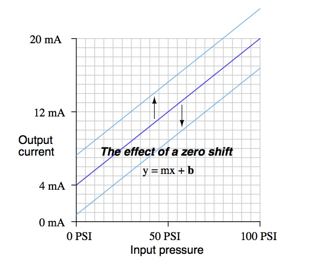
Proportional Control Action (P): The controller output responds in proportion to error signal. The characteristic equation for this action is:
  • Where, Kp is called proportional gain, e is the error magnitude and B is the output from controller when there is no error. It is also called bias. 
  • In a proportional controller, the value of gain is set as required by the process and can be varied from 0 to ∞. 
Integral Control Action (I): The control system will respond if the error is present over a period of time. This type of control action is called Integral Control Action. The integral action is defined mathematically as:
  • Where, e= error, Ti= Time interval of integral action.
  • Purpose of integral action is to provide adequate control action on varying demands of process. In this type of action, output varies as per the time integral of error. This action does not exist independently and always associated with proportional control. 
Derivative Control Action (D): To achieve a stable process, wide proportional band and low integral action are set. Due to these settings, the control system can be too slow. If large system disturbances occur over a wide interval, PI controllers are inadequate. These large system disturbances can be managed if the controller output responds not only to the magnitude of deviation, but also to the rate of change of deviation. Derivative control action is that control action. 

Today's process controllers are much easier to set the PID, thanks to auto-tuning algorithms. What used to be a very time consuming and tedious job can now be done with the push of a button and allowing the controller to "learn" the process dynamics. PID controllers minimize error and optimize the accuracy of any process.

For more information on the use of closed loop control with industrial inline process refractometers. contact Electron Machine Corporation by visiting http://www.electronmachine.com or calling 352-669-3101.

Understanding Error in Process Measurement

Instrumentation calibration is a procedure through which three general types of errors can be encountered. A typical signifier for a need of instrument recalibration is if the instrument is performing in an incorrect manner. This situation serves as a good way to showcase different types of error related to error analysis.

The three major category of errors regarding measurement are gross errors, systematic errors, and random errors. The first two categories of error, gross and systematic, are related to the two main elements of process control: controller and instrument. Gross errors are a product of the process controller or operator incorrectly evaluating the instrument value, with the best prevention of gross error being careful review of data both while recording and interpreting it.

Systematic errors impact every reading from a particular instrument, and are typically cause for instrument recalibration. Zero errors, where the instrument does not return to the predetermined zero value after each reading, are systematic errors because the same error in measurement is being displayed each time. Lastly, random errors impact instrumentation readings due to causes which are either unknown or simply unpredictable, meaning the error is both not able to be duplicated and is not a result of gross error. Random errors can be challenging to deduce due to both their singularity and their potential lack of a clear cause.

The previously mentioned zero error, also known as a zero shift calibration error, is typified by the resulting readings being offset at the same percentage. For example, a pressure transmitter which is functioning incorrectly as the result of a zeroing error can be corrected by a corresponding zero adjustment. After the adjustment and the transmitter being calibrated back to the correct zero point, the error will disappear. Another common type of systematic error is span shift calibration error. Unlike the zero error, span error can impact readings from the instrument repeatedly, but not necessarily identically. Similarly, by correcting the corresponding setting on the transmitter, in this case the span adjustment, the instrument can be correctly programmed once again by measuring the readings against a properly configured reference.

Hysteresis error occurs when the instrument in question returns erroneous responses as the input variable changes. The antidote to this kind of systematic error is to check the instrument against a pre-defined set of calibration points, first by increasing the input, and then subsequently decreasing the input in sequence to determine how the instrument responds as the input changes. Mechanical friction has been known to be a common culprit for hysteresis errors.

Understanding the capabilities and limitations of whatever instrument is relied upon for delivering process information is essential to successful operation.

Bleaching of Pulp in the Paper Making Process

The purpose of the bleaching process is to enhance the physical and optical qualities (whiteness and brightness) of the pulp by removing or decolorizing the lignin. Two approaches are used in the chemical bleaching of pulps. One approach called brightening, uses selective chemicals, such as hydrogen peroxide, that destroy chromatographic groups but do not attack the lignin. Brightening produces a product with a temporary brightness (such as newspaper) that discolors from exposure to sunlight or oxygen. The other approach (true bleaching) seeks to almost totally remove residual lignin by adding oxidizing chemicals to the pulp in varying combinations of sequences, depending on the end use of the product. This creates a longer lasting (sometimes permanent) whiteness, but it weakens the fibers and reduces sheet strength. The most common bleaching and brightening agents are chlorine, chlorine dioxide, hydrogen peroxide and sodium hydroxide.

Typically, the pulp is treated with each chemical in a separate stage. Each stage includes a tower, where the bleaching occurs; a washer, which removes bleaching chemicals and dissolved lignins from the pulp prior to entering the next stage; and a seal tank, which collects the washer effluent to be used as wash water in other stages or to be sewered. Bleaching processes use various combinations of chemical stages called bleaching sequences.

The first stage in the bleaching process is the chlorination stage, whose primary function is to further delignify the pulp. Chlorine reacts with lignin to form compounds that are water-soluble or soluble in an alkaline medium, which aids in delignifying the pulp before it proceeds to the next bleaching stage.

The next stage after chlorination is typically the extraction stage. This stage and the remaining stages serve to bleach and whiten the delignified pulp. The extraction stage removes the chlorinated and oxidized lignin by solubilization in a caustic solution.

Chlorine dioxide is often used in bleaching, either in the chlorination stage (as a substitute for some of the chlorine usage - chlorine dioxide substitution) or as an additional chlorine dioxide stage. Chlorine dioxide has 2.63 times greater oxidizing power (on a pound per pound basis) than chlorine and is used for nearly all high brightness pulps.

The next stage is the actual bleaching stage. Hypochlorite is a true bleaching agent that destroys certain chromophobic groups of lignin. It also attacks the pulp so high cellulose degradation occurs in Kraft pulp. Application of hypochlorite to Kraft pulp is usually used only as an intermediate stage of the sequence or to produce semi-bleached pulps. In the bleach process, residual chlorine must be removed through washing in vacuum washers.


Abstracted from Washington State
Air Toxic Sources and Emission
Estimation Methods

Sulfite Pulping

Pulping is the term used for the process which separates wood fibers. Chemical pulping, dissolving the lignin in the wood to create a pulp, is the most commonly used pulping process. Chemical pulping creates higher sheet strength than mechanical pulping; however, yields 40 to 50 percent pulp, where mechanical pulping yields 95 percent pulp.

The two main types of chemical pulping are the more common sulfate pulping (most commonly known as Kraft pulping) and sulfite pulping. Kraft pulping accommodates a variety of tree species, recovers and reuses all pulping chemicals, and creates a paper with a higher sheet strength. Sulfite pulp, however, is easier to bleach, yields more bleached pulp, and is easier to refine for papermaking. The major difference between the two types of chemical pulping is the types of chemicals used to dissolve the lignin.

Sulfite Pulping

The concept of sulfite pulping was created in the United States in 1867, however it was not used in a mill until 1874 by a Swedish chemist who was probably unaware of the U.S. Patent (MacDonald, 277). Sulfite pulping produces a lighter pulp than Kraft pulping. It can be used for newsprint, and when bleached can be used for writing papers and for the manufacture of viscose rayon, acetate filaments and films, and cellophane.

Description of Process 

Sulfite pulping follows many of the same steps as Kraft pulping. The major difference in sulfite pulping is that the digester “cooks” with a mixture of H2SO3 (sulfurous acid) and HSO3 ion in the form of calcium, magnesium, sodium, or ammonium bisulfate). The pulp continues on through the same processes as in the Kraft pulping process.

However, the chemicals separated from the pulp in the washers may or may not go into a recovery process. Chemical recovery in sulfite pulping is practiced only if it is economical. If chemical recovery does occur the liquor goes through an evaporator and then to a recovery furnace. Here, smelt is not formed, but ash and SO2 are formed.

Abstracted from Washington State
Air Toxic Sources and Emission
Estimation Methods

MPR E-Scan Deemed RoHS Compliant and Earns CE Marking

Electron Machine Corporation engaged F2 Labs for the technical assessment of the MPR E-Scan using the European standard, EN 50581:2012 Technical documentation for the assessment of electrical and electronic products with respect to the restriction of hazardous substances, to determine compliance with the RoHS Directive 2011/65/EU, and has determined Electron Machine Corporation can claim compliance to the RoHS Directive 2011/65/EU for the subject equipment based upon the supplied documentation.

RoHS stands for Restriction of Hazardous Substances. RoHS, also known as Directive 2002/95/EC, originated in the European Union and restricts the use of specific hazardous materials found in electrical and electronic products.

This certification applies to each portion of the MPR E-Scan (IS), which includes the Console, Cable, Barrier Box, and Sensing Head; along with all components that each of these major subassemblies of the MPR E-Scan contain.

For more information, please contact Electron Machine at 352-669-3101 or by visiting this link.

Paper Manufacturing: Kraft (Sulfate) Pulping

Abstracted from Washington State Air Toxic Sources
and Emission Estimation Methods

Pulping is the term used for the process which separates wood fibers. Chemical pulping, dissolving the lignin in the wood to create a pulp, is the most commonly used pulping process. Chemical pulping creates higher sheet strength than mechanical pulping; however, yields 40 to 50 percent pulp, where mechanical pulping yields 95 percent pulp.

The two main types of chemical pulping are the more common sulfate pulping (most commonly known as Kraft pulping) and sulfite pulping. Kraft pulping accommodates a variety of tree species, recovers and reuses all pulping chemicals, and creates a paper with a higher sheet strength. Sulfite pulp, however, is easier to bleach, yields more bleached pulp, and is easier to refine for papermaking. The major difference between the two types of chemical pulping is the types of chemicals used to dissolve the lignin.

The Kraft process was developed in Germany in 1879 and was first applied to a Swedish mill in 1885. The resulting paper was much stronger than any paper previously made, and therefore the process was named “Kraft”, (German and Swedish for “strength”). Kraft pulping creates dark brown paper which is used for boxes, paper bags, and wrapping paper. Kraft pulp can also be used for writing paper and paperboard when bleached, and for diapers when fluffed.

The three main steps involved in Kraft pulping are:
  1. Digestion: wood chips are cooked
  2. Washing: black liquor is separated from the pulp
  3. Chemical recovery: chemicals are recovered from the black liquor for reuse
Description of Process
  • Digestion 
The first step in pulping wood is to “cook” the wood chips. A digester, heated by steam, “cooks” the wood chips in white liquor (a mix of sodium hydroxide (NaOH) and sodium sulfide (Na2S)) until done. The cooking process dissolves most of the lignin and only some of the hemicellulose , leaving mostly cellulose to hold the fibers together. The digester system may be a batch or a continuous process.

Relief gases are vented continuously from the digester, which helps remove air and other non- condensable gases and reduce the pressure at blow, when the pulp is discharged to the blow tank. After the cooking process, the pulp and black liquor (the chemical mix left after the cooking process) are discharged to a blow tank.

By-products can be recovered from the digestion process. For example, turpentine distills with water out of the blow tank and the evaporators and is separated to be used. The resin acids and fatty acids dissolved from the wood form sodium soaps which are skimmed off the black liquor from storage tanks, evaporators, and black liquor oxidation tanks, and then acidified with sulfuric acid to form tall oil.

Before the washing process, the pulp is usually sent to deknotters, screens used to remove knots (large pieces of fiber not completely broken down in the digester).
  • Brownstock Washing 
Pulp from the blow tank and deknotter is washed with water in a process commonly called brownstock washing. Washing removes weak black liquor from the pulp which is sent to the chemical recovery process. This also prevents contamination during subsequent processing steps. Types of washers used include rotary vacuum washer (most common type of washer), diffusion washers, rotary pressure washers, horizontal belt washers, wash press, and dilution/extraction.

All the washer types use water (fresh or recycled) and are usually placed in series to achieve higher removal efficiency.

The rinsed pulp is screened for oversize particles and then excess water is removed. This is done in a gravity thickener (more commonly known as a decker).
  • Chemical Recovery 
The reason Kraft pulping is economically successful is that the used cooking liquor can be recovered and reused in the chemical recovery process.

The first step in recovering the chemicals from the black liquor is evaporation. This removes excess water from the black liquor and maximizes the fuel value for the recovery furnace.

There are two types of evaporators generally used in the chemical recovery process: direct (DCE) and indirect (NDCE) contact evaporators. Some types of DCE include the multiple-effect evaporator (most common), flash evaporation and thermocompressor evaporation. DCE use heat from direct contact with the recovery furnace flue gases, while NDCE uses indirect contact.

Black liquor oxidation is needed after DCE, but not after NDCE. After DCE, the black liquor is normally oxidized with air to control the sulfide level and prevent the release of odorous compounds. This is done by countercurrently passing the black liquor through an air stream using a porous diffuser, sieve tray tower, packed tower or agitated air sparge. The oxidation reaction converts sodium sulfide to sodium thiosulfate.

After NDCE or black liquor oxidation, the black liquor is then forced through spray nozzles into the recovery furnace, where it is burned providing heat to generate steam. This also conserves the inorganic chemicals, which create a molten smelt on the floor of the furnace.

The molten smelt, composed of sodium sulfide and sodium carbonate, is drained from the recovery furnace hearth through smelt spouts. In a smelt dissolving tank, the smelt is quenched with water, producing green liquor.

Sodium carbonate from the smelt is then converted to sodium hydroxide in the causticizer by adding calcium hydroxide. The calcium carbonate resulting from the reaction precipitates from the solution and is collected and sent to the lime kiln where it is converted to lime (calcium oxide). The calcium oxide is then slaked to produce calcium hydroxide for reuse in the causticizer.

Hybrid-Digital Process Refractometer

hybrid-digital critical angle refractometer
Process refractometers are used for monitoring, controlling, and recording the concentration of dissolved solids in a process media. They accurately measure refractive index and temperature of the process media and provide a visual display in units specific to that process (i.e. Brix, Percent Solids, Dissolved Solids, SGU, R.I.).

The MPR E-Scan is a hybrid-digital critical angle refractometer. It is used to measure the refractive index of process fluids and may be used as an error indicator or an integral part of a complete process control system.

The MPR E-Scan is calibrated and temperature compensated to your process specifications. It is ready for installation and immediate use when received. Calibration procedures are available to change system parameters and allow the refractometer to measure different process fluids.

How It Works: Hybrid-Digital Measurement

hybrid-digital critical angle refractometerEnergy radiated from the LED passes through the prism surface to be reflected off a mirror to the prism-to-process interface. The light reaching this interface intersects the same interface over a series of angles specifically chosen to include the critical angle (Ic) for the process being measured. Light intersect- ing the interface at an angle greater than critical angle is refracted into the solution. Light intersecting the interface at less than critical angle is reflected up out of the prism up to the digital CCD linear array to be scanned.

The resolution of each sensing head is maximized by selecting the angle of the prism for the measurement and temperature range of the process.

MPR E-Scan
MPR E-Scan
The MPR E-Scan refractometer utilizes a hybrid-digital measurement principle. The CCD (charged coupled device) in the sensing head digitally measures the refractive index of the process. Any change in critical angle changes the ratio of light to dark periods. The digital measurement is temperature compensated and converted to a variable voltage by rugged electronic devices in the sensing head. This allows the relatively sensitive micro-processor driven devices to be located in the electronics console where more protection from the process can be provided. The signal is then further enhanced and displayed as a reading in refractive index, Brix, solids, percent, or other measurement unit. This combination of state-of-the-art micro-processors combined with tried-and-true analog components provides a high-level of accuracy along with the rugged dependability required for years of use when installed in harsh industrial environments.

hybrid-digital critical angle refractometer